

PWO: Faster to Finished Sheet Metal Forming Tools with Optical Metrology
Company‘s place of business: Oberkirch
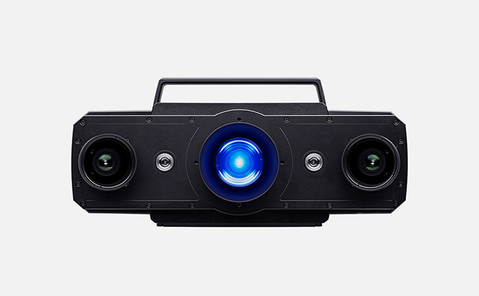
GOM system: ATOS Triple Scan
GOM software: GOM Inspect Professional
Sector: Toolmaking
PWO
PWO is one of the world‘s leading developers and manufacturers of sophisticated metal components and systems in the field of lightweight construction for automotive safety and comfort. Over its 98-year history since its foundation in 1919, the group has developed unique expertise in forming and joining metals. PWO‘s German site in Oberkirch currently employs approximately 1,500 people. With additional sites in the Czech Republic, Can- ada, Mexico, and China, PWO is represented worldwide. In total, the group employs more than 3,100 people.

Progress-Werk Oberkirch (PWO) relies on optical 3D metrology from GOM in its tool shop. As a result, the company is able to reduce tool startup times and increase productivity.
One of the key requirements of the German automotive industry is to reduce the time to market in the face of increasing demands on quality control. This is having an impact in toolmaking too. To remain competitive, it is vital to reduce tool startup times and improve quality, as only perfectly developed and produced tools will guarantee customers an impeccable final product.
One company meeting the high customer demands of firms such as VW, BMW and Mercedes-Benz is automotive supplier PWO. The core expertise of the group, which was founded in 1919, is primarily in stamping, drawing, bending, transfer, and progressive tools. PWO‘s products range from tools for the manufacture of motor housings, motor mounts or air springs to tools for airbag components. Each year, the company produces up to 70 tool sets, in some cases consisting of 14 individual stages.
To meet the special requirements generated by the various tools, PWO has been using the ATOS Triple Scan from GOM since 2010. The non-contact 3D scanner is used both during manufacturing and tool tryout and when servicing and maintaining them.
Optical Metrology Reduces Development Times
Due to the large number of changes, the tryout process involves several weeks of trial and error for each tool- maker. The individual contouring and geometry of the sheet metal parts must be tested and measured each time, and the tool subsequently reworked. The use of tactile measuring machines is a particularly time-intensive process during the tryout. Thus, measuring a part can often take several hours. In addition, each individual measuring point must be programmed in beforehand.

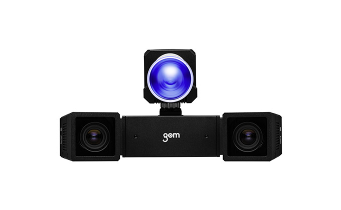
PWO aimed to shorten this process by purchasing the ATOS non-contact 3D scanner. Instead of spending hours on tactile measuring procedures, PWO now captures shapes, individual parts, and active elements – i. e. any parts that are actively involved in the cutting, bending, and forming process – quickly and without contact. The sensor is accurate down to a few hundredths of milli- meter, depending on the measuring volume. To carry out the measurement, the scanner projects a fringe pattern onto the measuring object, which is distorted by the component‘s contour. This distortion is recorded by two cameras, each with 16 million measuring points per scan, and used as the basis for a point cloud, which precisely visualizes the component‘s surface.
“Besides the time that is saved, it‘s the full-field represen-tation of the component‘s surface that is a major advan- tage,” explained Wilfried Braun, Head of the measuring room at PWO. “A full-field, color plot visualization of the component‘s geometry at a glance is very informative.”

Most notably, this simplifies its comparison against CAD. Specific measuring points can also be output if needed. “In this way, you can see directly where something doesn‘t quite fit and errors in the tool can be rectified immediately with specific correction values,” explained the metrology specialist. In addition to inspecting sur- faces, 3D digitizing provides benefits when measuring features that are typical of sheet metal, as sharp-edged features such as hole patterns, trimming and spring are precisely captured.
Comparing the measured actual data against CAD additionally enables simulation results to be checked, so that simulation parameters can be adapted where necessary. If it becomes clear during the measurement that the sheet metal part is out of tolerance, the problem can be swiftly analyzed and fixed. “Overall, you get more information with less effort.”
 |
 |
Optimum Component Alignment Reduces Iteration Loops
ATOS reduces the time required to measure a complex active element such as a forming punch from 4 – 5 hours to a mere 30 minutes. For a nominal/actual comparison, the scanned data is then transformed into the desired coordinate system using a best-fit function. During this alignment process, the measured active part is virtually aligned to the lowest overall deviation from the reference point. The ideal alignment results in the component having the smallest possible deviation from CAD. Thus, relevant points can also be selectively inspected. If the crucial points for the measuring object are within the toleranced surfaces, the surface contour is dimensionally accurate overall and functional rejects are reduced.
If there is in fact a tolerance deviation, PWO immediately starts the tool correction and surface reconstruction using measuring data from the ATOS Triple Scan system. The surface reconstruction is particularly suitable in order to bring data sets of manually reworked tool elements up to date. If the active part is showing signs of wear, for example, the spare parts can be quickly produced during ongoing operations and based on current data, which optimizes production times. In addition, the archived data sets can be consulted again at any time for servicing or repairs at a later date.
Flexible Measuring System for Different Object Sizes
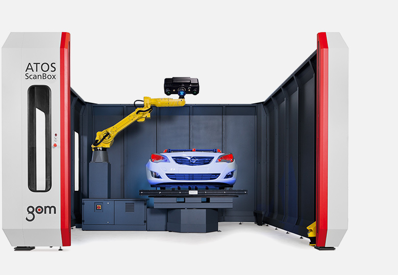
Another advantage of the sensor is its mobility. If you have a bigger part, the scanner can be transported on the stand to the object at any time. “From time to time, the complete tool is measured directly in the press line. This can be car- ried out quickly and simply using the flexible ATOS system,” explained the measurement engineer. In addition, the concept of an end-to-end system solution encompassing soft- ware, hardware and training, meets PWO‘s requirements. “If there are any technical questions, we have a contact person who knows the toolmaking requirements and our process chain, and has an overview of the big picture.”

Metrology Systems for Sheet Metal Forming
 |
 |
 |
 |
Bring quality, precision, speed and reliability to your production proccessAIE provides the total 3D metrology solutions from GOM to industrial customers and mechanical research institutes and universities in Vietnam. Contact us for free consultation today.
|