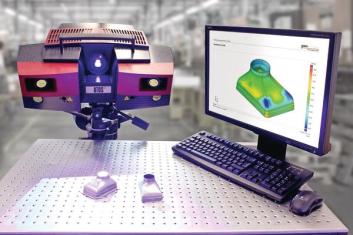
Getting the tool perfectly right for complex sheet metal parts used to involve a long trial-and-error process. But now the Bernecker Group has combined a CAD/CAM solution with a simulation software and optical metrology. Thus, the company achieved a substantial reduction in the number of tool iterations.
Higher engine power requirements in the automotive industry go hand in hand with ever more stringent exhaust gas limit values. In order to meet the tight standards, turbochargers are increasingly combined with a downstream exhaust gas recirculation (EGR) system to reduce the engine’s untreated NOx emissions – a solution implemented in the new VW Golf GTD, for instance. “This technology is becoming increasingly popular because emission limit values cannot be met without it,” reports Thilo Maisenbacher, Head of Design at Bernecker.
Despite Bernecker’s wealth of experience in the production of sheet metal parts gained over many years, the EGR – which is composed of several stainless steel sheet profiles – poses new challenges for the company’s tool specialists. This is because in the production of the EGR (and an increasing number of other components) customers request that a defined percentage reduction in thickness resulting from an ironing operation must not be exceeded. Taking account of this percentage in the tool design and then checking it on the manufactured component is quite an undertaking. Copyright © 2014 GOM mbH All rights reserved! Rev. A (en) 120614 www.gom.com 3 Intelligent link between design, simulation and measurement To ensure faultless development and production of ironed parts meeting the specification, Bernecker has created an integrated design, simulation and measurement solution: a process loop from 3D design using the VISI CAD/CAM system, simulation using the Stampack simulation software with springback calculation, VISI Advanced Modelling for springback compensation, right up to fast optical 3D measurement with a high-resolution digitizer, the ATOS system from GOM – and back in reverse order. The size of the objects that can be measured with the ATOS system ranges from a few millimeters to several meters. The measuring accuracy for small parts such as the EGR is in the region of hundredths of a millimeter. To perform the measurement, a fringe pattern is projected onto the object. The distortion due to the object’s contours is captured by two cameras. The resulting images are used to compute a point cloud that depicts the component surface precisely. Full-field measurement of a component is the advantage of this method, which gives the user a digital view of the entire component so that potential problems can be identified instantly.
Bernecker has recently started to use the ATOS system’s fast measurement capabilities for its tool development operations, too. First of all, the tool is designed in 3D with the VISI software before the geometrical data are copied to the Stampack system to simulate the part. The tool specialists then compensate for the springback calculated using the integral Advanced Modelling module in the VISI CAD system. It is this optimized tool version that is then used on the machine tool. “We measure the part manufactured with this tool by means of the ATOS 3D digitizer from GOM, compare the results with the existing 3D model and make corrections if necessary,” explains Thilo Maisenbacher. “Using the Advanced Modelling feature, we once again correct any remaining springback, adjust the tool, produce the part, and then measure it with the ATOS digitizer. And then it fits.”

Bernecker has been using the VISI 3D CAD/CAM software and Stampack simulation software for several years for fast and simple tool design and simulation. The idea to round off this solution by adding the ATOS system to create a closed iteration loop emerged much later. Initially, Bernecker used to cut open the manufactured parts. In a time-consuming process the thinnest portion produced by the ironing operation was identified using tactile measurement. That was until Bernecker learned from Men at Work that GOM data could be used in VISI CAD without any difficulties. Men at Work, an IT and engineering service provider based in southern Germany, sells CAD/CAM solutions and simulation software. The mesh data acquired in a GOM measurement can be transferred effortlessly to the VISI system for easy further processing. Working in VISI, the designer can add sections to the GOM mesh data. Bernecker uses this feature to reproduce old tools, for example. This is necessary because there are many old tools in use which have to manufacture spare parts for up to 15 years. In many cases, drawings no longer exist, partly because some of the tools are customer-supplied models. Today, when defects occur, the parts are measured on the GOM machine or the mobile measuring system is simply taken to the tool to be measured. Once the tool has been measured, a 3D drawing is created in VIS.
Source: www.gom.com


